Layout Smps Full Bridge
This smps will be the power source of full bridge rf amplifier, amplifying sine wave(500 khz) to few thousand volts (ex: Efficiency is the primary benefit, with efficiencies over 90% for many designs.
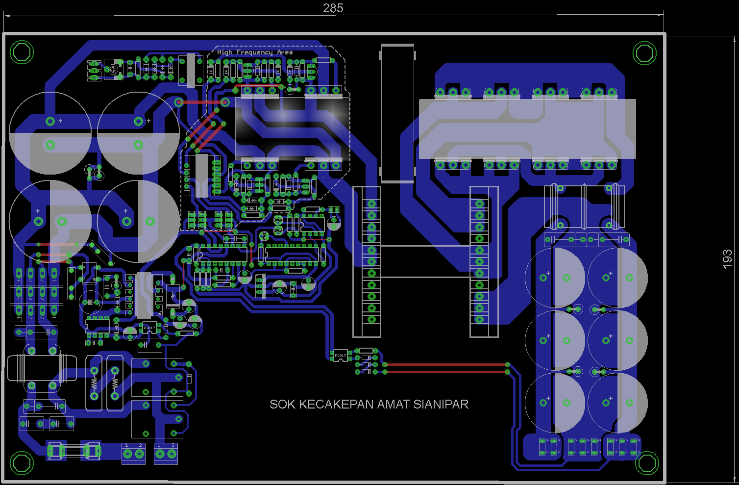
Pcb SMPS Full Bridge Pfc
You have 17 pri turns, so you are around 1900 gauss.

Layout smps full bridge. In our designs, we'll typically consider bmax to stay within the range 1300g to 2000g. If its your first time building a smps then i suggest you. It helps readers understand and build an active bridge line rectification device more easily.
Having full bridge needs more winding on the trafo and the circuit will be more complicated and more care is needed. Switching mode power supply full bridge pfc schematic and pcb Small size and reasonable cost are.
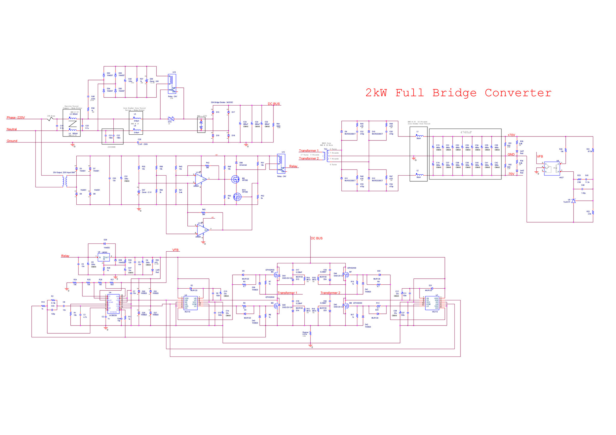
Switching mode power supply full bridge pfc schematic and pcb A design example is provided for a power supply with the following specifications: Figure 1 shows a simplified circuit of a phase shifted full bridge.
Design of active bridge line rectification for smps about this document scope and purpose this document is an application note describing the design and operation of active bridge line rectification. Should you be accustomed to applying tesla or millitesla (t or mt) for flux density, remember 1t = 104gauss. Poweresim is free smps power supply design, manufacturer & product database/list, switching converter topologies, circuit analysis, magnetic design software, transformer/inductor simulation & calculation software, dvt, differential mode emi simulation, emi measurement, harmonics, thermal, mtbf, life time and monte carlo analysis tool.
Post that value, any increase in smps voltage, vout becomes unstable and varies randomly. It support led driver design, pfc,. Similarly, qc and qd are switched at 50 % duty and 180 degree out of phase with each other.
Qa and qb are switched at 50 % duty and 180 degree out of phase with each other. Design is optimized for the 170 mω 600 v coolmos™ cfd7 js mosfet device, namely ipp60r170cfd7. Full bridge is usually used for more power above 1000 watts.
Half bridge and push pull is 1/2 controller frequency and full bridge is same frequency as controller. B (max) actually is determined by the design and the transformer cores used. You should change your controller frequency to 50khz.
B (max) = maximum flux density in gauss. Efficiency tends to be better with full bridge as less current is needed for the same power due to the primary voltage is double. This effectively doubles the voltage across the primary, and fewer turns are needed on the secondary for a given output voltage.
At 1600 gauss a conservative value for older ferrites you would have 20 pri turns at 50 khz. With the initial design and development of smps in place, the rf amplifier is able to work properly with smps vout values upto 70 v. Excel file for designing a switch mode power supply.
Power supply (smps) design offers reduced component count, high reliability and flexibility to have modular construction to reuse the designs.
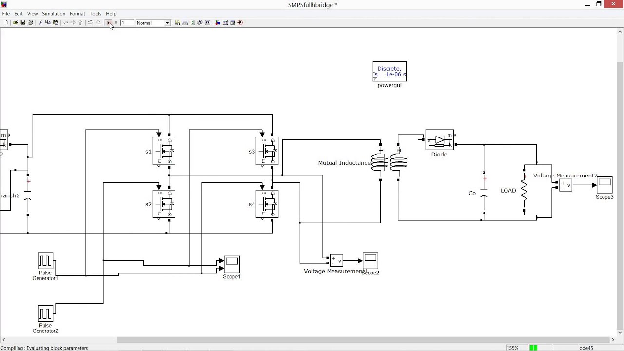
FULL H BRIDGE BASED SMPS SIMULATION MATLAB SIMULINK
sg3525 full bridge inverter sechmatic with pcb layout SHEMS


SMPS FULLBRIDGE PFC Schematic + PCB Layout PDF

Full Bridge Smps Transformer Design
pcb layout smps full bridge schematic SHEMS

sg3525 smps schematic full bridge SHEMS

How To Design Smps Transformer

pcb layout smps full bridge schematic SHEMS

2kW Full Bridge SMPS Dizaynı Kontrol Kalemi Forumları
sg3525 full bridge inverter sechmatic with pcb layout SHEMS

sg3525 smps schematic full bridge SHEMS


Skema Power Supply Tv China TV Schematics
membuat smps full bridge SHEMS


smps circuit diagram pdf fresh finding a power supply

Pcb SMPS Full Bridge Pfc

PhaseShift FullBridge Controller Enables Efficient

PCB Layout ClassD D2K FB (Full Bridge) 2000W Electronic

Full Bridge Smps Transformer Design
SMPS TopoMagic